|
ARCHITECTURAL ID |
PICTURE VIEW
|
TITLE |
DWG FILE |
DATE POSTED |
|---|
|
05 Metals |
| | |
|
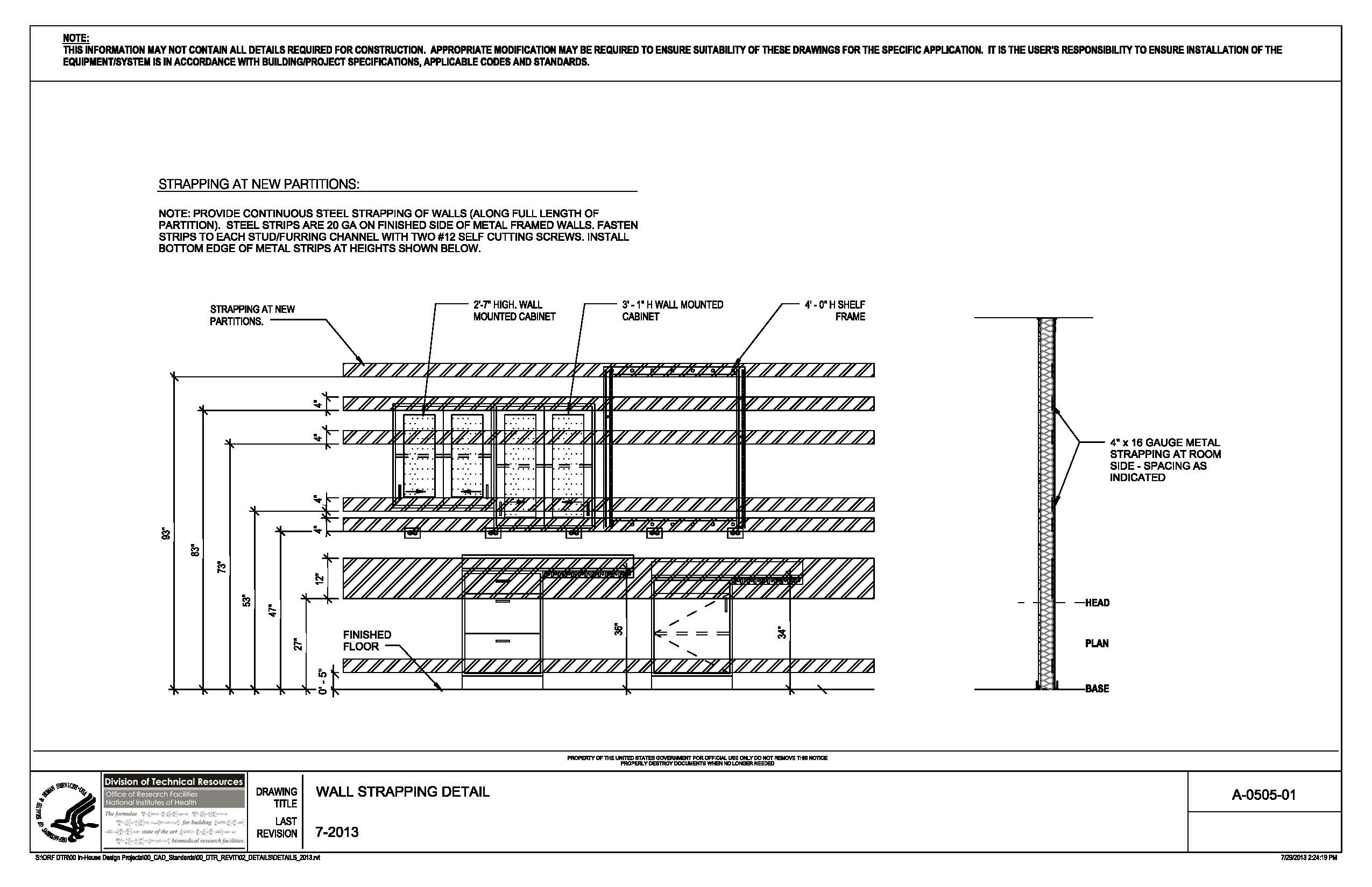
A-0505-01
|
(335KB) jpg |
Wall Strapping |

167KB |
07/31/2013 |
|
06 Wood, Plastics, Composites | | | | |
|
A-0640-01 | |
Benchtop Grommet Plan |
110KB |
07/31/2013 |
|
08 Openings | | | | |
|
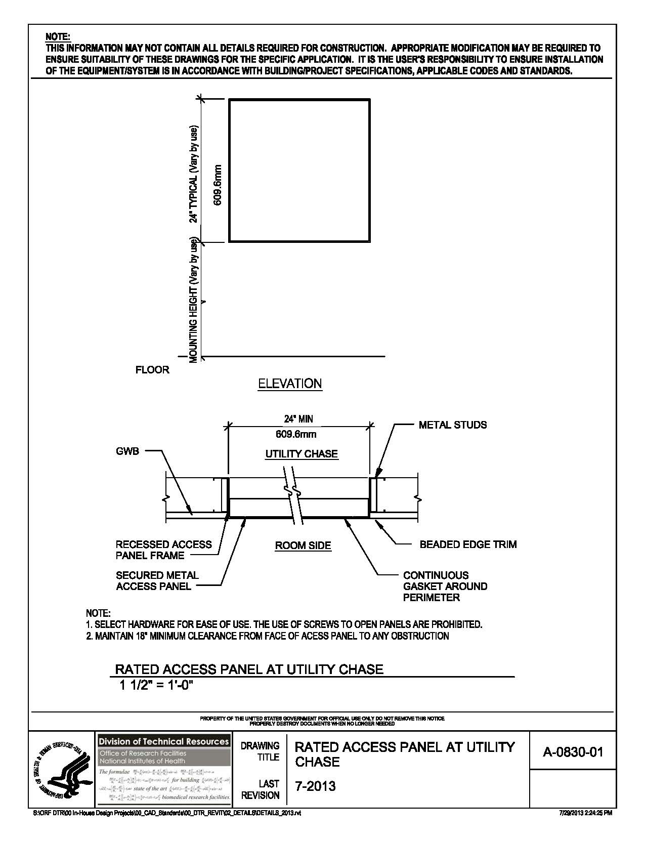
A-0830-01 |
(182KB) jpg |
Rated Access Panel Utility Chase |
84KB |
07/31/2013 |
|
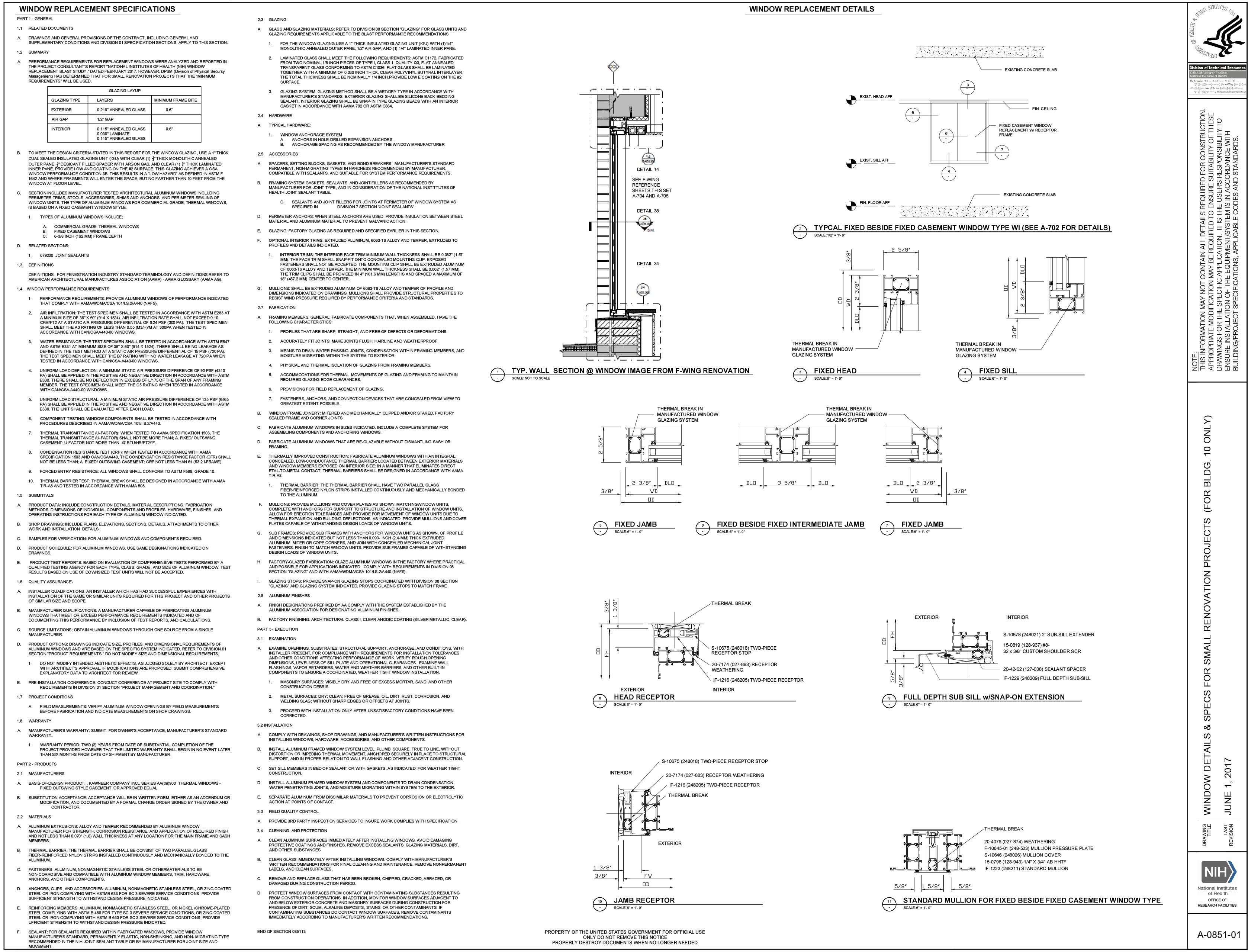
A-0851-01 |
(1.23MB) jpg |
Window Details & Specs For Bldg 10 |
814KB |
06/01/2017 |
|
09 Finishes | | | | |
|
A-0960-01 |
(649KB) jpg |
Floor Transition Typ. |
70KB |
08/26/2013 |
|
A-0960-05 |
(600KB) jpg |
Floor Trans - Integral Base |
69KB |
08/26/2013 |
|
10 Specialties | | | | |
|
A-1010-02 |
(269KB) jpg |
Post-Doc Desk With Divider Panel Section |
81KB |
08/20/2013 |
|
A-1010-06 |
(279KB) jpg |
Divider Panel Section |
83KB |
08/20/2013 |
|
A-1020-01 |
(145KB) jpg |
Corner Guard 01 |
80KB |
07/31/2013 |
|
A-1020-02 |
(196KB) jpg |
Corner Guard 02 |
91KB |
07/31/2013 |
|
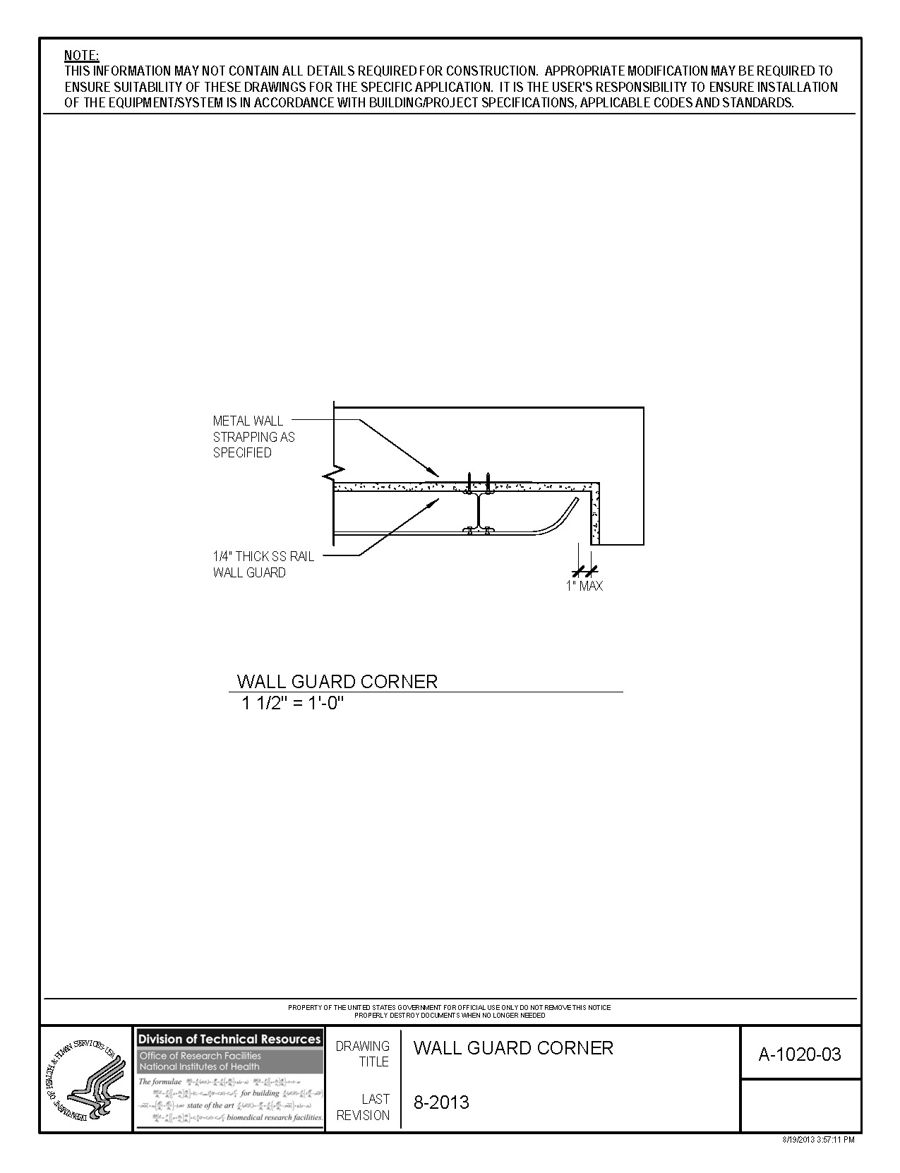
A-1020-03 |
(210KB) jpg |
Wall Guard Corner |
58KB |
08/26/2013 |
|
12 Furnishings | | | | |
|
A-1230-01 |
(304KB) jpg |
Removable Back Panel |
106KB |
07/31/2013 |
|
A-1230-03 |
(189KB) jpg |
Typical Benchtop |
85KB |
07/31/2013 |
|
A-1230-04 |
(208KB) jpg |
Typical Peninsula Casework Section Type 01 |
111KB |
07/31/2013 |
|
A-1230-07 |
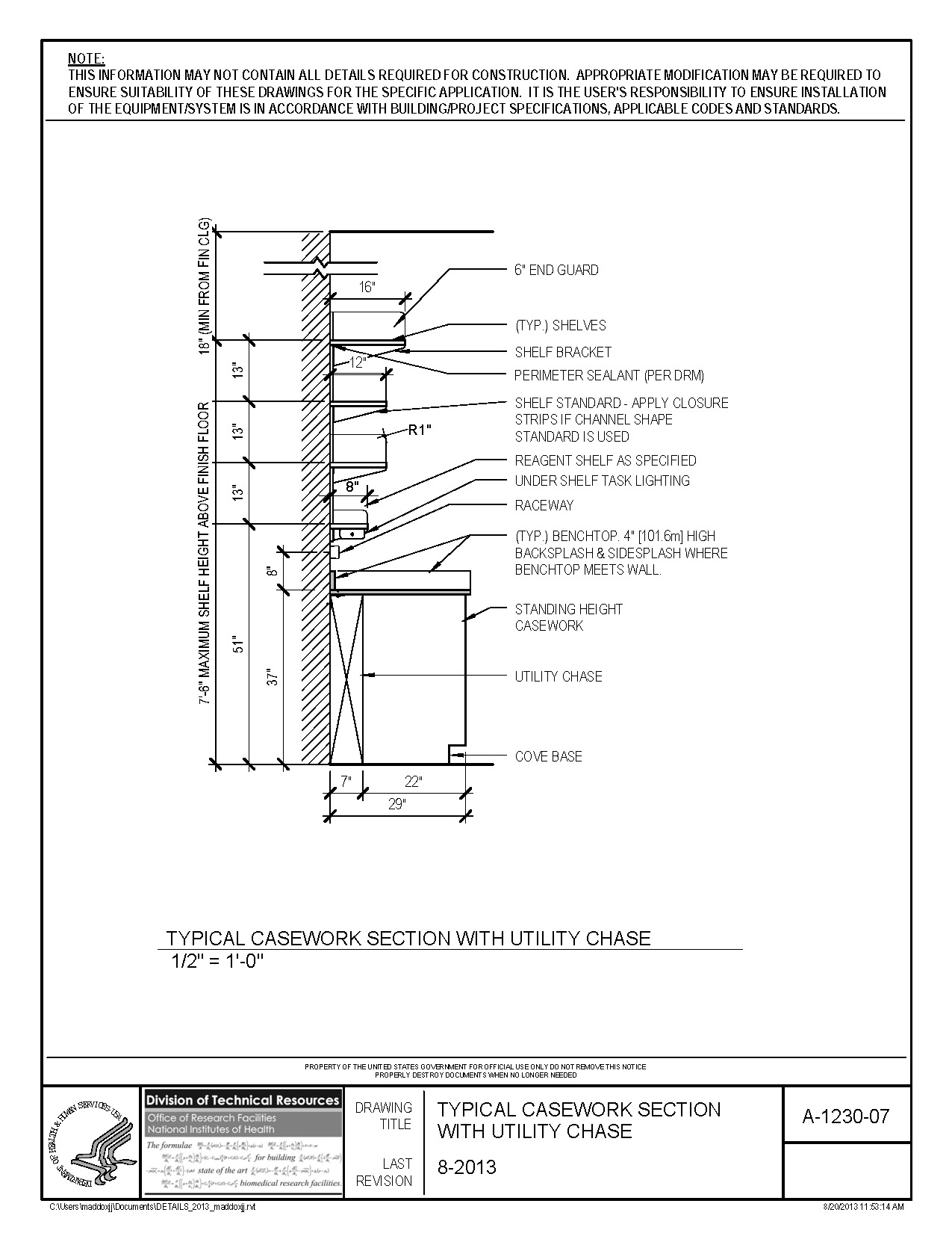
(313KB) jpg |
Typical Casework Section with Utility Chase |
79KB |
08/26/2013 |
|
A-1230-08 |
(733KB) jpg |
Typical Casework Section at Wall |
75KB |
08/26/2013 |
|
A-1230-13 |
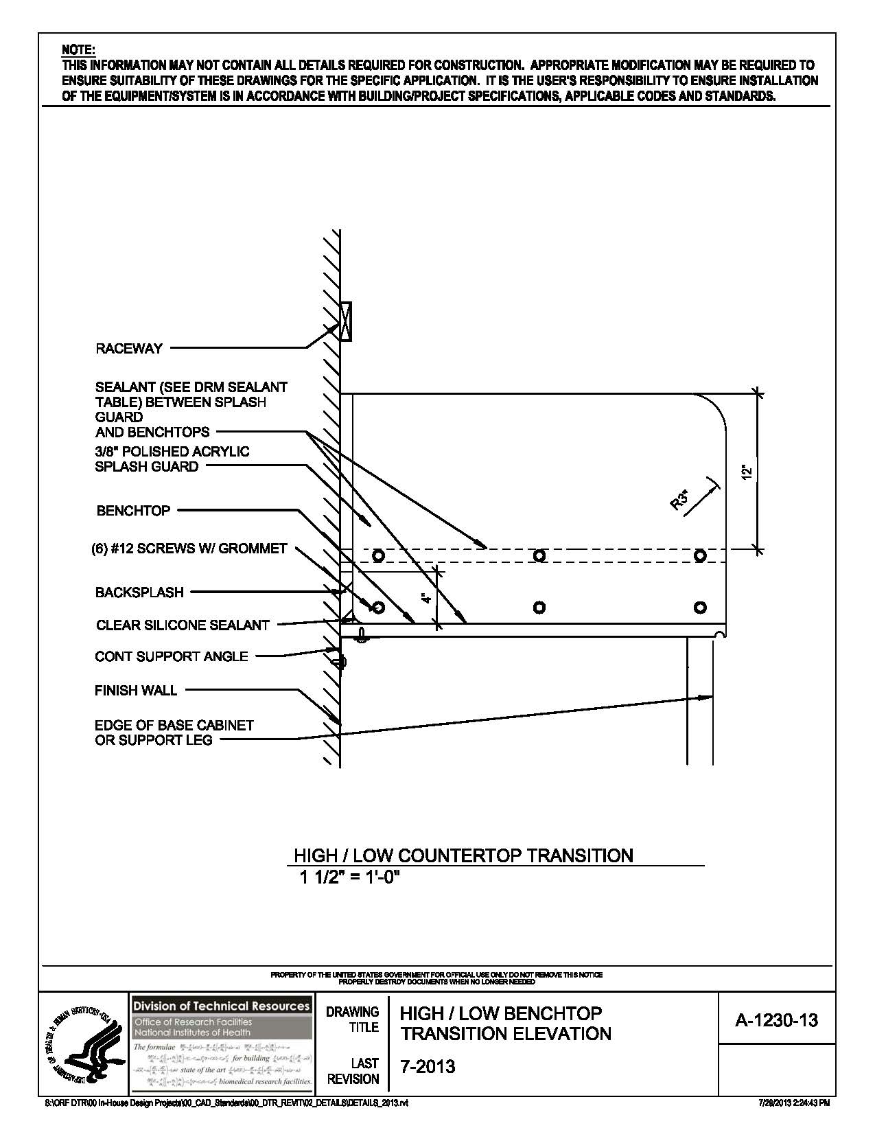
(188KB) jpg |
High / Low Benchtop Transition Elevation |
89KB |
07/31/2013 |
|
A-1230-20 |
(214KB) jpg |
Benchtop Service Fitting Type 02 |
90KB |
07/31/2013 |
|
A-1240-01 |
(215KB) jpg |
Graduated Cylinder Shelf |
91KB |
07/31/2013 |
|
A-1240-02 |
.jpg)
(243KB) jpg |
Benchtop Drip Edge |
56KB |
08/26/2013 |
|
A-1240-05 |
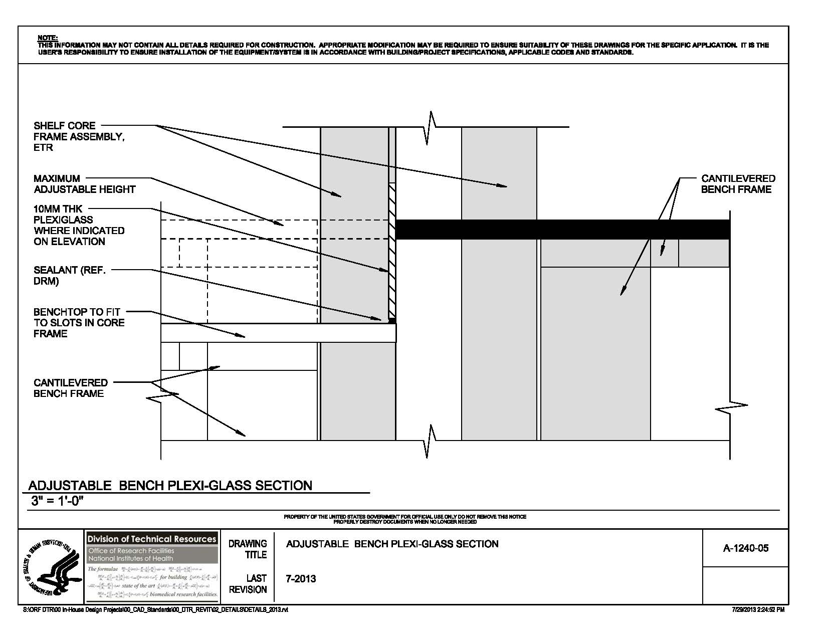
(177KB) jpg |
Adjustable Bench Plexi-Glass Section |
87KB |
07/31/2013 |
|
A-1240-07 |
(177KB) jpg |
Peninsula Shelving |
82KB |
07/31/2013 |
|
A-1240-10 |
(278KB) jpg |
Cylinder Restraint Single Bracket |
58KB |
08/26/2013 |
|
A-1240-11 |
(284KB) jpg |
Cylinder Bracket Side by Side |
60KB |
08/26/2013 |
|
A-1240-12 |
(268KB) jpg |
Cylinder Bracket Front to Back |
59KB |
08/13/2013 |
|
A-1240-16 |
(272KB) jpg |
Splashguard Section |
89KB |
07/31/2013 |
|
A-1240-20 |
(171KB) jpg |
Pegboard |
98KB |
07/31/2013 |
 to top
 | | | | |
|
PICTURE VIEW |
TITLE |
DWG FILE |
DATE POSTED |
|---|
|
20 Normal Power | | | | |
|
E-20-01 |
(160KB) jpg |
Interstitial Space Panel Mounting |
223KB |
01/03/13 |
|
30 Emergency Power | | | | |
|
E-30-01 |
(176KB) jpg |
Separately Derived Generator System Grounding |
197KB |
01/03/13 |
|
40 Site | | | | |
|
E-40-01 |
(94KB) jpg |
Typical Handhole |
284KB |
06/27/12 |
|
E-40-02 |
(123KB) jpg |
Typical Electrical Manhole |
184KB |
06/27/12 |
|
E-40-03 |
(257KB) jpg |
Typical Communications Manhole |
223KB |
06/27/12 |
|
E-40-04 |
(198KB) jpg |
Manhole Cover |
191KB |
06/27/12 |
|
E-40-05 |
(179KB) jpg |
Manhole Cable Rack |
202KB |
06/27/12 |
|
E-40-06 |
(211KB) jpg |
Ductbank Section |
268KB |
06/27/12 |
|
E-40-07 |
(199KB) jpg |
4-Way Ductbank |
254KB |
06/27/12 |
E-40-08
|
(213KB) jpg |
6-Way
Ductbank |
293KB |
06/27/12 |
|
E-40-09 |
(240KB) jpg |
10-Way
Ductbank |
332KB |
06/27/12 |
|
E-40-10 |
(248KB) jpg |
12-Way Ductbank |
336KB |
06/27/12 |
|
E-40-11 |
(171KB) jpg |
Tele-LAN Ductbank Elevation |
315KB |
06/27/12 |
|
50 Raceways, Conduit & Boxes |
| |
|
|
|
E-50-01 |
(180KB) jpg |
Vertical Busduct Floor Penetration |
409KB |
01/04/13 |
|
E-50-02 |
(197KB) jpg |
Conduit Installation in Concrete Construction |
269KB |
01/04/13 |
|
E-50-03 |
(165KB) jpg |
Pipe Sleeve Thru Wall |
203KB |
01/04/13 |
|
E-50-04 |
(168KB) jpg |
Caste In Place Sleeve for Raceway |
206KB |
01/04/13 |
|
E-50-05 |
(158KB) jpg |
Electrical Wiring Through Fire & Fire Smoke Barriers |
198KB |
01/04/13 |
|
E-50-06 |
(200KB) jpg |
Piping Support Above Ceiling |
202KB |
01/04/13 |
|
E-50-07 |
(167KB) jpg |
Piping Support at Roof |
195KB |
01/04/13 |
|
E-50-08 |
(276KB) jpg |
Surface Metal Raceway Assembly |
259KB |
01/04/13 |
|
E-50-09 |
(299KB) jpg |
Surface Metal Raceway Wiring |
261KB |
01/04/13 |
|
E-50-10 |
(154KB) jpg |
Receptacle Wiring |
216KB |
01/04/13 |
|
E-50-11 |
(171KB) jpg |
Recessed Cast Box Installation |
197KB |
01/04/13 |
|
E-50-12 |
(275KB) jpg |
Electrical Wiring Configuration - System Furniture |
250KB |
02/04/13 |
|
60 Power Quality & Grounding | | | | |
|
E-60-01 |
(153KB) jpg |
Dry Type Transformer 600V or Less Grounding |
203KB |
01/04/13 |
|
E-60-02 |
(257KB) jpg |
Building Grounding Electrode System |
208KB |
01/04/13 |
|
E-60-03 |
(211KB) jpg |
Building Electrical System Ground Bus |
212KB |
01/04/13 |
|
E-60-04 |
(194KB) jpg |
Building Telecommunication System Ground Bus |
204KB |
01/04/13 |
|
E-60-05 |
(185KB) jpg |
Isolated Ground Receptacle Wiring Diagram |
241KB |
01/04/13 |
|
70 Lighting | | | | |
|
E-70-01 | |
Pole Base |
272KB |
06/27/12 |
|
E-70-02 | |
Extended Pole Base |
272KB |
06/27/12 |
|
E-70-03 | |
BSL3 Lab Lighting Installation |
279KB |
06/27/12 |
|
E-70-04 | |
Typical Lighting Fixture Installation |
318KB |
06/27/12 |
|
80 Miscellaneous | | | | |
|
E-80-01 | |
Flat Surface Air Terminal Mounting |
280KB |
06/27/12 |
|
E-80-02 |
(158KB) jpg |
Adjustable Point-Base & Air Terminal |
277KB |
06/27/12 |
|
E-80-03 | |
Exhaust Discharge Stack Lighting Protection |
275KB |
06/27/12 |
|
E-80-04 | |
Down Lead to Ground Connection |
325KB |
06/27/12 |
|
E-80-05 |
(139KB) jpg |
Ground Rod Structural Steel Connection |
276KB |
6/27/12 |
|
E-80-06 |
(188KB) jpg |
Lightning Conductor Down Lead Penetration |
284KB |
06/27/12 |
|
E-80-07 |
(201KB) jpg |
Typical Lab Bench Elevation |
201KB |
01/04/13 |
|
to top | | | | |
|
GENERAL ID |
PICTURE VIEW | |
DWG FILE |
DATE POSTED |
|---|
|
G-SR01-SB |
(80KB) jpg |
Signature Review Stamp Block |
200KB |
11/23/11 |
|
G-TB01-8.5X11 |
(106KB) jpg |
Division of Technical Resources Title Block 8.5X11 |
447KB |
03/25/13 |
|
G-TB01-11X17 |
(141KB) jpg |
Division of Technical Resources Title Block 11X17 |
650KB |
04/22/13 |
|
G-TB01-24X36 |
(449KB) jpg |
Division of Technical Resources Title Block 24X36 |
366KB |
04/22/13 |
|
G-TB01-30X42 |
(618KB) jpg |
Division of Technical Resources Title Block 30X42 |
372KB |
04/22/13 |
| | | | |
|
MECHANICAL ID |
PICTURE VIEW | |
DWG FILE |
DATE POSTED |
|---|
|
A Air Side | | | | |
|
M-A2-1 |
(216KB) jpg |
Duct Penetration through Masonry or Concrete |
383KB |
01/04/13 |
|
M-A2-2 |
(201KB) jpg |
Duct Penetration through Stud Wall |
557KB |
01/04/13 |
|
M-A4-1 |
(251KB) jpg |
Air Terminal (Shut-Off) Unit Installation |
156KB |
11/22/11 |
|
M-A7-2 |
(140KB) jpg |
Conical Duct Fitting |
242KB |
12/21/12 |
|
M-A8-1 |
(149KB) jpg |
Exhaust Air Terminal Unit |
193KB |
01/04/13 |
|
M-A9-1 | |
Freeze Protection Thermostat Installation |
472KB |
11/22/11 |
|
C Control | | | | |
|
M-C1-1 |
(210KB) jpg |
Fan Coil Unit Control Diagram |
245KB |
01/04/13 |
|
E Equipment | | | | |
|
M-E4-1 |
(241KB) jpg |
End Suction Pump |
513KB |
12/21/12 |
|
M-E4-2 |
(263KB) jpg |
Horizontal Split Case Pump |
406KB |
12/21/12 |
|
M-E4-3 | |
In Line Pump Piping Installation |
148KB |
11/22/11 |
|
M-E4-4 | |
In Line Pump with Redundancy Piping Installation |
149KB |
11/22/11 |
|
M-E8-1 |
(247KB) jpg |
Exhaust Fan Stack |
222KB |
12/21/12 |
|
M-E10-1 |
(436KB) jpg |
Exposed Cabinet Type Fancoil Unit Piping |
248KB |
01/04/13 |
M-E11-1
|
(252KB) jpg |
Electric Condensate Return Unit |
238KB |
12/21/12 |
|
SCHD Schedule | | | | |
M-SCHD-1
|
(399KB) jpg |
Induction Unit Schedule
(For Old Building 10 Only)
|
315KB
|
01/10/18
|
|
S Steam | | | | |
|
M-S1-1 | |
End of Run Steam Drip Trap Assembly |
149KB |
11/22/11 |
|
M-S1-2 |
(177KB) jpg |
Drip at End of Steam Supply |
149KB |
11/22/11 |
|
M-S2-1 | |
HP Vertical - Flash Tank Piping |
153KB |
11/22/11 |
|
M-S2-2 | |
Low Pressure Horizontal-Flash Tank Piping |
218KB |
12/21/12 |
|
M-S2-3 | |
MP Vertical - Flash Tank Piping |
153KB |
11/22/11 |
|
M-S2-4 |
(241KB) jpg |
Vertical Flash Tank with Steam Recovery |
255KB |
01/04/13 |
|
M-S9-1 | |
LP Duct Mounted Steam Humidifier Piping |
152KB |
11/22/11 |
|
M-S10-1 |
(165KB) jpg |
Steam Condensate Lift to Overhead Return |
241KB |
01/04/13 |
|
W Water Side | | | | |
|
M-W2-1 |
(226KB) jpg |
Multiple Chilled Water Coil - Piping |
156KB |
11/22/11 |
|
M-W3-1 | |
HW Reheat Coil Piping (2-way valve) |
166KB |
11/22/11 |
|
M-W3-2 | |
HW Reheat Coil Piping (3-way valve) |
179KB |
11/22/11 |
|
M-W3-3 |
(244KB) jpg |
Preheat Glycol Solution HW Coil Piping |
233KB |
12/21/12 |
|
M-W4-1 | |
Bladder Type Expansion Tank - Vertical |
185KB |
11/22/11 |
|
M-W5-1 | |
Cooling Coil Drain |
156KB |
11/22/11 |
|
M-W5-2 | |
Pipe Drain Installation |
252KB |
11/22/11 |
|
M-W5-3 | |
Safety Relief Valve |
198KB |
11/22/11 |
|
M-W5-4 |
(258KB) jpg |
Water Tight Sleeve |
273KB |
12/21/12 |
|
M-W5-5 | |
Air Vent |
192KB |
11/22/11 |
|
M-W5-6 |
(221KB) jpg |
Cored Slab Pipe Support |
260KB |
12/21/12 |
|
M-W5-7 |
(170KB) jpg |
Core Drilled Pipe Sleeve |
242KB |
12/21/12 |
|
M-W5-8 |
(200KB) jpg |
Water Softener Piping |
236KB |
12/21/12 |
|
M-W5-9 |
(206KB) jpg |
Glycol Make-Up System |
250KB |
12/21/12 |
|
M-W5-10 |
(250KB) jpg |
Typical Pipe Hanger |
299KB |
12/21/12 |
|
M-W5-11 |
(235KB) jpg |
Pipe Saddle Support |
265KB |
01/04/13 |
|
M-W5-12 |
(203KB) jpg |
Pipe Support |
250KB |
01/04/13 |
|
M-W5-13 |
(193KB) jpg |
Temperature Instrument Port |
249KB |
01/04/13 |
|
M-W6-1 |
(272KB) jpg |
Chilled Water Flat Plate Heat Exchanger
|
242KB |
12/21/12 |
| | | | |
|
PLUMBING ID |
PICTURE VIEW | |
DWG FILE |
DATE POSTED |
|---|
|
G Gases | | | | |
|
P-G1-2 |
(247KB) jpg |
Utility Ledge |
253KB |
01/04/13 |
|
P-G1-3 |
(211KB) jpg |
Fume Hood Piping Diagram |
256KB |
01/04/13 |
|
S Sanitary & Vent | | | | |
|
P-S1-1 | |
Sanitary Vent thru Roof |
199KB |
11/22/11 |
|
P-S1-2 |
(147KB) jpg |
HUB Drain with Back Water Valve |
329KB |
12/21/12 |
|
P-S1-3 |
(171KB) jpg |
Indirect Waste (Sanitary) |
284KB |
12/21/12 |
|
W Water | | | | |
|
P-W1-1 | |
Reduced Pressure Backflow Preventer |
227KB |
11/22/11 |
|
P-W2-1 | |
Emergency Shower |
191KB |
11/22/11 |
|
to top | |
| |
|